
thallia
Project Hype: LED Spectrum Analyzer
Project Introduction
As I’ve been out of school for a little over a month now, I’ve needed some fun projects to keep me busy while waiting to hear back from internship applications. I’ve been browsing the current trends on Instructables, and one of the projects caught my eye: 7-Band LED Audio Visualizer
This was a great and clever project, and around a year ago I wanted to design one of my own after seeing videos like this:
Isn’t that amazing?
I thought to myself how cool these things were, and now that I have more electronics experience under my belt, it didn’t seem like too hard of a project. I grabbed my notebook and started designing.
Components
| Component | Quantity |
|---|---|
| 3.5mm Audio Jack | 1 |
| DC Power Jack | 1 |
| MSGEQ7 DIP | 1 |
| LPD8806 SOP | 7 |
| Arduino Nano | 1 |
| 0.1uF Capacitor | 2 |
| 0.01uF Capacitor | 1 |
| 33pF Capacitor | 1 |
| 22kOhm Resistor | 2 |
| 200kOhm Resistor | 1 |
| 3.3kOhm Resistor | 24 |
| 1kOhm Resistor | 12 |
| 20kOhm Resistor | 48 |
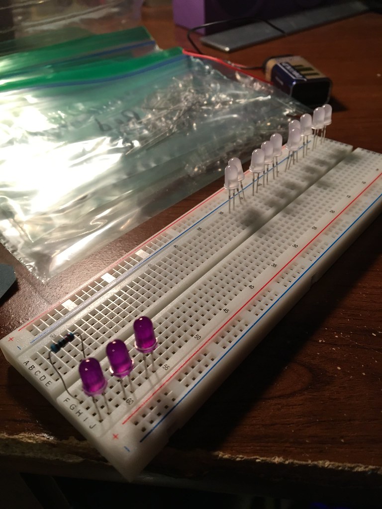
| 5mm Diffused Green LED | 48 |
| 5mm Diffused Yellow LED | 24 |
| 5mm Diffused White LED | 12 |
| 1/4” Black Acrylic | 1 |
For the brains of this project, I chose to go with the simple MSGEQ7 Seven Band Graphic Equalizer. It’s a chip that takes an audio input and divides it into 7 different frequencies, which are multiplexed onto an output and can be sent to other devices.
I didn’t want to use LED strips, since I didn’t like the way they look and I really wanted to design my own encasing, so I looked up the driver they use for the typical LED strips and found the LPD8806 chip. Lemme tell ya, those things are hard to find to purchase online, but I found a fairly cheap source from AliExpress: LPD8806 SOP-16 Chip
These chips are simple and addressable LED drivers, so you can access each individual LED that you want. They have 6-outputs, so I’ll be using quite a few of these. You can read more about different LED strips and drivers here. That was a helpful reference for me as I was trying to understand how they work and what different types there were.
The rest of the components consist of the actual LEDs I’m using, the resistors for the LEDs, and simple decoupling capacitors for the MSGEQ7 chip.
Since I wanted there to be purple LEDs in my project, and all the purple LEDs on the market are UV, I ended up taking diffused white LEDs and coloring them purple with a purple sharpie, and it created the perfect soft light purple glow that I wanted.
Schematic

Here is the roughed out first version of the schematic, I only put two of the LPD8806s on there since it’d be repetitive, as far as I read on the LPD8806 datasheet you simply string together their SDI/SDO and SCLKI/SCLKO together to use multiple in a row.
Hardware Encasing
As I was in the designing phase of the project, I didn’t just want to create another LED Spectrum analyzer that looked the same as everyone elses. Straight and square, how boring is that? I took to my notebook and drew out some rough ideas of what the encasing could look like, and came up with these:

I ended up going with the top idea, a plant-like design with the little dots being all the LEDs. I decided to have the encasing be black acrylic, and that I’d laser engrave the design onto it. I got to work sketching it out on my Huion drawing tablet, using Krita as the drawing software.

I took that design, and that was the engraving. But I still needed some pretty precise dimensioning done for the LED holes, so I downloaded CorelDRAW 2019 and used their free 16-day trial. We use CorelDRAW at my college for our trotec laser cutter, so I was familiar with the software already.
I bought a sheet of 1/4” Black acrylic from amazon, it’s really good quality.
I was able to position and get all the circles on the picture, and exported it to the laser cutter at my friend’s school after putting the files on a flash drive.
Here’s a picture of what it looked like when being sent to the laser cutter (the red circles are really thin!):

The first time we engraved it, it was unfortunately a flop, they’re still experimenting with their laser cutter since it was pretty new and the settings had to be messed with, so we ended up just doing the cut line so I could have a reference for where to put the LEDs until we could have more time to engrave it later.
I took the flop cut and used it as a reference for the LEDs, and started soldering all the GNDs together:

I used some basic craft wire to solder all the grounds to, which will make it easier in the end to not have a bunch of ground wires going everywhere.
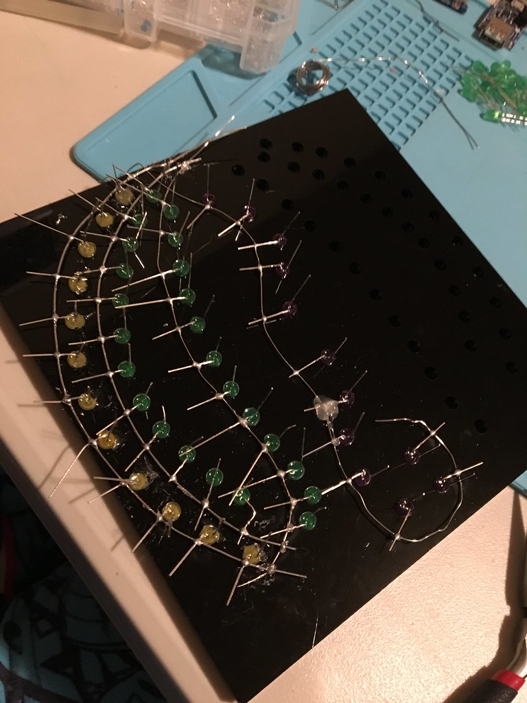
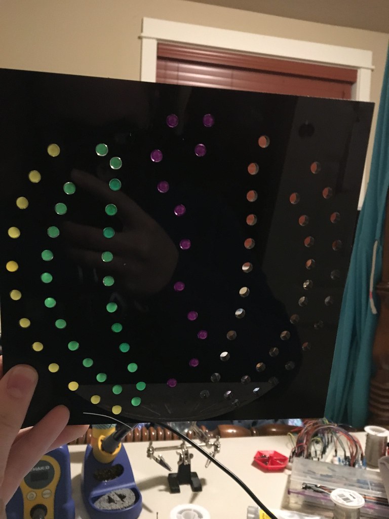
It looks pretty silly without the engraving behind it, but I figure I’d get a head start on the circuitry so I can pop the LEDs right into the new one when I get it. Sometimes flops are great, since you can use them for structure prototyping!
Next Steps
The SOP-16 breakout boards (you can find thousands of them on eBay) and the LPD8806s are on their way, so I’ve started envisioning the rest of the circuit layout and begun thinking about the code. Stay tuned for the next installment, coming soon!
Happy designing,
{thallia}