
thallia
Project Hype: Chore Tracker (P.D.A.)
Project Introduction
I’m well on through my second semester at college, and this semester our engineering class is focusing on the electrical and computer engineering side of things (as opposed to last semester, which was mostly mechanical). The challenge this time is to design a product you could develop with an arduino, and market it.
There are themes each semester, and this semester’s theme is smart children’s and baby’s products. Kind of a difficult category to go with, but we can work with it.
We were put into teams to work on this project together, and we all decided to go for a variant of smart children’s products by going more along the lines of smart tools parents can use with children. Eyy, how about that!
We came up with quite a few ideas, but settled on the idea of a chore tracker, something that would help parents manage which children perform which tasks, and provide a fun interface for the child to complete chores with that’s not located on a device.
There are a variety of chore tracker print-outs, games, and apps out there, but we thought it would be ideal if the tracker stayed away from being located on a device itself, like a parent’s phone, or iPad, or a computer, since it would be aimed towards the idea of the child completing their chores before earning access to their devices. We also thought it more useful than the charts with stickers or magnets, since it would be more interactive, would last much longer than paper or a sticker, and things like magnets wouldn’t get lost over time.
Our final theoretical idea became a tablet-like object that would sit on the counter and act as a chore tracker, instead of using an application or something that could grow old real fast.
In my previous post, I had just started planning out the coding and the circuitry for the project.
Many months have past, and we’re almost at completion.
Electronic Components
| Components | Links |
|---|---|
| RA8875 Driver | https://www.adafruit.com/product/1590 |
| Arduino UNO | https://www.amazon.com/ELEGOO-ATmega328P-ATMEGA16U2-Arduino-Compliant/dp/B01EWOE0UU |
| Adafruit TFT 7” Screen | https://www.adafruit.com/product/2354 |
| MicroSD Card Reader | https://www.amazon.com/gp/product/B01JYNEX56/ |
| SD Card | https://www.amazon.com/SanDisk-Mobile-MicroSDHC-SDSDQM-B35A-Adapter/dp/B004ZIENBA |
| 74HC125N Tri-State Buffer | https://www.amazon.com/gp/product/B00B88A030/ |
| Prototyping Shield | https://www.amazon.com/Alloet-Breadboard-Prototyping-Prototype-ProtoShield/dp/B01N55OWBY/ |
| Prototyping Board | https://www.amazon.com/ELEGOO-Prototype-Soldering-Compatible-Arduino/dp/B072Z7Y19F/ |
Circuitry
I mentioned in the previous post that I had some potential SPI issues when stringing the SD card and the 7” TFT together with the same SPI pins on the Arduino.
The solution to this was tying SCK and MOSI together between the SD card and the RA8875 driver, and defining the chip-selects as different in the code. When you do that, you can easily string multiple SPI Devices together!
MISO Tri-State Buffer
But there was one drawback that I didn’t realize until I actually wired it all together. I had made the assumption that you could tie MISO together as well, but when reading the RA8875 Datasheet, I found that the MISO pin on the RA8875 is not tri-state.
There is a phenomena called tri-state pins, where there are three states the pin can be in: high, low, and high-impedance. High obviously means 5V, low means -5V or 0V, and high impedance means it’s floating, and doesn’t have a value. This is an important state in certain devices, such as the Arduino, but unfortunately the RA8875’s MISO pin didn’t support a tri-state.
So I had to go back to the schematic board with this one and add a tri-state buffer to my circuit. This would allow the MISO pin on the RA8875 and the MicroSD Card Reader be able to be connected to the Arduino’s MISO pin through the tri-state buffer. For the chip, I used a SN74HC125N from Texas Instruments (link to product is above).
SN74HC125N Pinout
Here is the basic pinout of the tri-state buffer, from the datasheet:

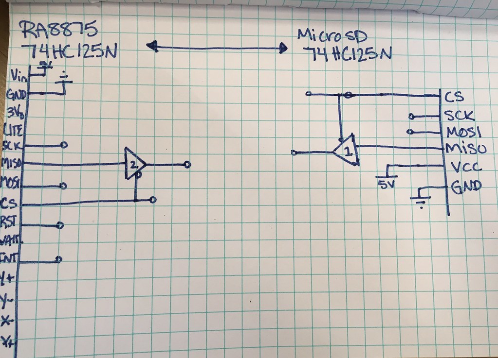
And the theoretical connections with the RA8875 and MicroSD Card Reader:
Pinout
| Device: | Arduino UNO | MicroSD Reader | RA8875 |
|---|---|---|---|
| Pin: | 13 (SCK) | SCK | SCK |
| 12 (MISO) | tri-state buffer | buffer | |
| 11 (MOSI) | MOSI | MOSI | |
| 10 | CS | ||
| 9 (w/ resistor) | RST | ||
| 7 | CS | ||
| 3 | INT |
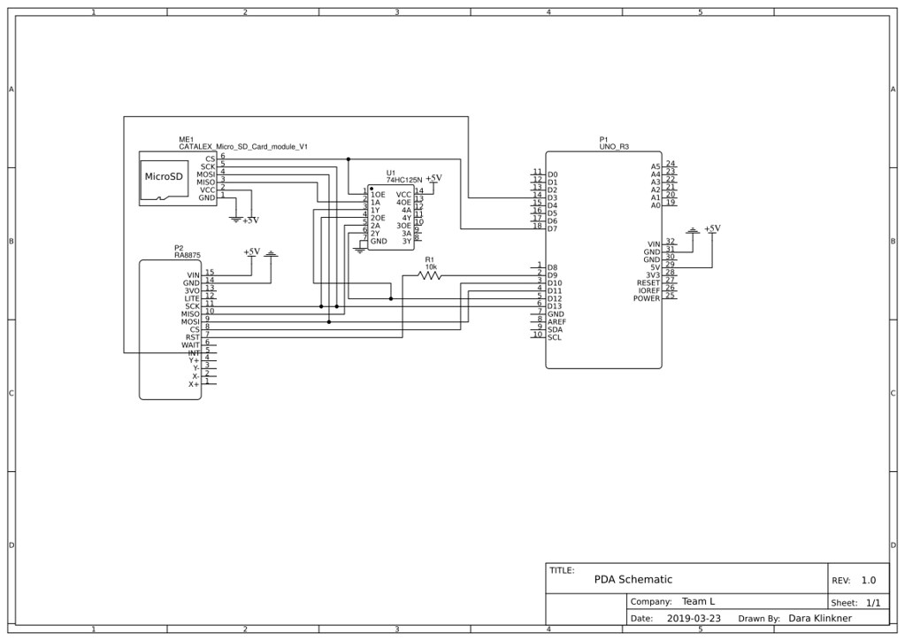
Official Schematic
Mechanical Drawings / Project Encasing
For the encasing of our product, we have a simple acrylic base, with a wood finish on top.

We have yet to machine the parts, but we’ve gotten the 3D printed part started, and will finish the laser cut part soon. Hopefully in the next week or two we can get the rest of the parts machined and tested for sizing adjustments.
Code
I’ve been working on coding and circuitry for the project, especially for the last two weeks in the coding part of it, and so far I have had lots of success. Making a program that interfaces with an SD card and a touchscreen is rather difficult, but it works.
The main loop of the code uses a basic switch case:
switch (currentState) { // currentState is going to be displaying the homescreen initially

    case HOMESCREEN:
      // display the homescreen
      homeScreen();

    case CHORES: // next state will be if they press the chore display button
      // display the child data and ask what day of chores they want to see
      choreList();
      //break;

    case DAY:
      // this is going to, based on the day picked, display the chores due that day
      displayDayChores();
}
And the majority of the rest of the code are functions that I coded myself, as you can see with homeScreen() and the others. This makes it a really simple loop of code, and I can edit it “outside” of the main loop.
RA8875 Library
The RA8875 Library was a bit of a code to crack at first (no pun intended), but it’s fairly simple once you read into it and see some of the examples.
The main files I got my information from were the header files and the C++ source file.
The header file I found most useful for quick glances of what functions I needed to use and what arguments they required.
The most common set of functions I used was all the below:
  /* Text functions */
  void    textMode(void);
  void    textSetCursor(uint16_t x, uint16_t y);
  void    textColor(uint16_t foreColor, uint16_t bgColor);
  void    textTransparent(uint16_t foreColor);
  void    textEnlarge(uint8_t scale);
  void    textWrite(const char* buffer, uint16_t len=0);

  void    drawRect(int16_t x, int16_t y, int16_t w, int16_t h, uint16_t color);
  void    fillRect(int16_t x, int16_t y, int16_t w, int16_t h, uint16_t color);

   /* Touch screen */
  void    touchEnable(boolean on);
  boolean touched(void);
  boolean touchRead(uint16_t *x, uint16_t *y);
The text functions allow you to set the color(textTransparent()), scale(textEnlarge()), and where you want to write the text(textSetCursor(x, y)) onto the 7” TFT screen.
I mostly used rectangles for the GUI, filled (fillRect(x, y, w, h, color)) and unfilled (drawRect(x, y, w, h, color)), and text to display the rest of what was needed.
You can see my current code here
With four weeks left of the semester I have a good chunk of stuff to catch up on for this project, but look forward to an update with the final project then! Contact me if you have any questions about my process or are just curious about how I went about something! I’d love to hear from you.
Until next time,
{thallia}