
thallia
Project Hype: Oscillating Air Engine
My first semester of college has been quite the adventure. I’ve met a group of great nerds, I’ve been having a great time with my classes, and midterms are in just a few days. I wanted to take some time to update on our engineering semester project: designing and building an oscillating air engine.
For the first few weeks of class, our professor gave us the assignment of studying the engine: what are the main eight components that make it run?
We were able to study engines for the next week–didn’t matter whether we got the official names of the parts right or wrong, just as long as we could name them and describe how they interact and make the rest of the engine work.
The eight parts (with official names) are as follows:
    Flywheel
    Crankdisc
    Crankshaft
    Piston
    Cylinder
    Crankpin (e-pin)
    Valve plate (intake)
    Base plate (exhaust)
The engine is pretty neat, it works like this: compressed air is attached to the intake hole–which fills the cylinder. When full, the air pushes the piston out of the cylinder. The piston is attached to the e-pin (which is in turn connected to the crankdisc), and as the piston pushes the crankdisc, the crankdisc (which is attached to the crankshaft) spins the crankshaft with it. As the crankshaft spins, finally, that spins the flywheel. The flywheel is a really big hunk, usually of metal. The momentum of that continues until the cylinder crosses the exhaust hole, which lets out all the compressed air, and the piston is pushed back into the cylinder.
Ain’t that cool?
After that, we were given orthographic and isometric drawings of an engine, and tasked with figuring out the geometric variables that related all the holes together. Everything is related, and you can’t just guess the dimensions or else the engine could lock while spinning, never spin in the first place, or worse.
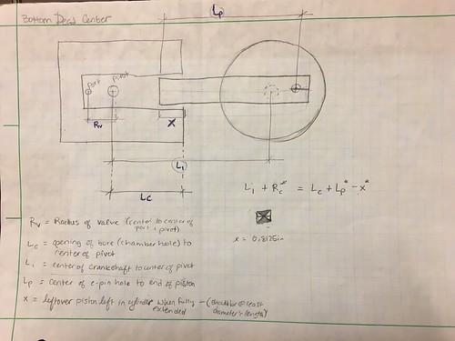
Here were the variables, and the equations that related them:
Rv = Radius of valve - distance from pivot to port
Lc = opening of bore to center of pivot
L1 = center of crankshaft to center of pivot
Lp = center of e-pin hole to end of piston
x = leftover piston left in the cylinder when fully extended (should be at least the diameter's length)
Rc = crank radius - distance from e-pin to center of crankshaft
2v = distance between intake and exhaust holes

equation 1: (L1 + Rc = Lc + Lp - x)
equation 2:  sin(θ) = Rc/L1
equation 3: sin(θ) = v/Rv
equation 4: cos(θ) = h/Rv
Once those were figured out and we knew how they worked together mathematically, we had to take the theoretical drawings of our engines (mine are pictured below) and figure out the geometric variables for them.

Boy, that was a time. My friends and I all found so many mistakes in the ideas that we’d had for our engines, but it didn’t take long to assess the issue, come up with a new idea, and implement it!
Now that we had all the theoretical math figured out, it was time to decide on a goal for the engine, create a bill of materials, and start 3D modeling.
There are 5 goals you could aim for in building the engine:
   Max speed/RPM
   Max torque/power
   Max coast
   Air efficiency
   Cost efficiency
I originally started with max torque/power, but I ended up changing, and you’ll see why.
My engine design looks like this:
My hypotheses were that if I had two offset pistons, they could compensate for each other’s lack of force at the momentum-carrying part of the cycle. If I had a large flywheel, that could account for more momentum, and speed, and it could pull more. There’s also a creativity goal, so I made the triangles because I thought that’d be interesting looking.
To get our engines approved, we had to go through 3 levels: have the geometry approved by the professor, have the 3D modeling and theory of how your engine works approved by a mechanic dude, and have our official machining drawings approved by a professional machinist. That last one is especially hard–not many people tend to get approved, you had to make sure your drawings were very polished and conveyed all the correct information, but also be careful that they weren’t over-dimensioned. That was a lot to get done, but I was up to the challenge.
My geometry was approved pretty fast–all my holes lined up and everything seemed to work alright!
My build was approved as well, and the mechanic gave me some good suggestions. Based on the design of my engine, there was no way to test the torque. The tool used to test torque has to grab onto the crankshaft, but unfortunately I have pistons in the way on both sides of my design. The mechanic recommended that I change my goal: perhaps to speed, because I have a lot going for me in that category. He also recommended that I changed a few hardware pieces that I had, so I adjusted those in my bill of materials.
When I turned in my drawings, I was a bit wary since they were fairly simple. All the parts of my engine were very simple, and we got to choose one part of our engine to CNC, so I didn’t have to machine my complicated triangular valve plate. The next day, my drawings were in–and they were approved!!

What’s really cool is the other day, I was working in the 3D printing lab, and a sophomore mechanical engineer saw me, and we struck up a conversation. He shared with me his engine design when he was a freshman, and ended up giving me some advice on mine as well, which was great. He said that the triangles are a great idea for speed–since a 45* angle is the best operating angle, as well as a large flywheel. That definitely encouraged my goal of max speed that I’m now going for, and I’m looking forward to seeing how it all works out.
So far, I’ve completed my crankshaft, base plates, and one of my pistons. One piston, two crank discs, and my flywheel to go!
Until next time, nerds!
{thallia}