ArkenPi - Origins (hardware)
Final list of materials:
-
Raspberry Pi 3 Model B
-
MicroSD Card (32GB)
-
Adafruit PiTFT 3.5” PLUS Touchscreen
-
Lithium-Ion Polymer Battery (1200mAh)
-
Wireless Bluetooth Keyboard
-
5.5V to 3.3V step down converter
-
Adafruit Powerboost 1000c
-
Female USB Connectors
-
Male USB Connectors
-
MicroUSB POWER ONLY Cord (short)
-
Power switch
-
Wifi Adapter (optional)
-
2x 3mm LEDs
-
2x 200ohm resistors
-
A 3D Printed case OR hack your own out of hard drive cases
Tools:
-
soldering station
-
pliers (round nose)
-
tweezers
-
knife
-
wire cutters
-
solder
-
hookup wire (stranded recommended)
-
electrical tape
-
hot glue gun + glue
-
(opt) helping hands
-
patience
Before assembling anything, I had to get the Pi3 to boot with the Adafruit PiTFT plus, which was a pain in the butt. The adafruit website declared,
“The display uses the hardware SPI pins (SCK, MOSI, MISO, CE0, CE1) as well as GPIO #25 and #24. GPIO #18 can be used to PWM dim the backlight if you like. All other GPIO are unused.”
I found that to be false info. I scratched my head trying to figure out how to find which pins were being used and which ones weren’t, and I came up with the brilliant and monotonous idea of connecting 40 jumper wires from the PiTFT to the Pi 3. I disconnected each pin one at a time to see if it would boot correctly, then removed the jumper wire if it wasn’t needed. In thirty minutes, I had the right pins to get the Pi to boot onto the TFT.

Using the chart above helped a lot (credit to whoever’s chart it is), and here are the GPIO pin numbers I came up with, and their functions:
pin 1 - 3.3V PWR
pin 2 - 5V PWR
pin 9 - GND
pin 18 - GPIO24 (GPIO_GEN5)
pin 19 - GPIO10 (SPI0_MOSI)
pin 21 - GPIO9 (SPI0_MISO)
pin 22 - GPIO25 (GPIO_GEN6)
pin 23 - GPIO11 (SPI0-_CLK)
pin 24 - GPIO8 (SPI_CE0_N)
pin 26 - GPIO7 (SPI_CE1_N)
pin 27 - ID_SD (I2C EEPROM)
pin 28 - ID_SC (I2C EEPROM)
Assembly:
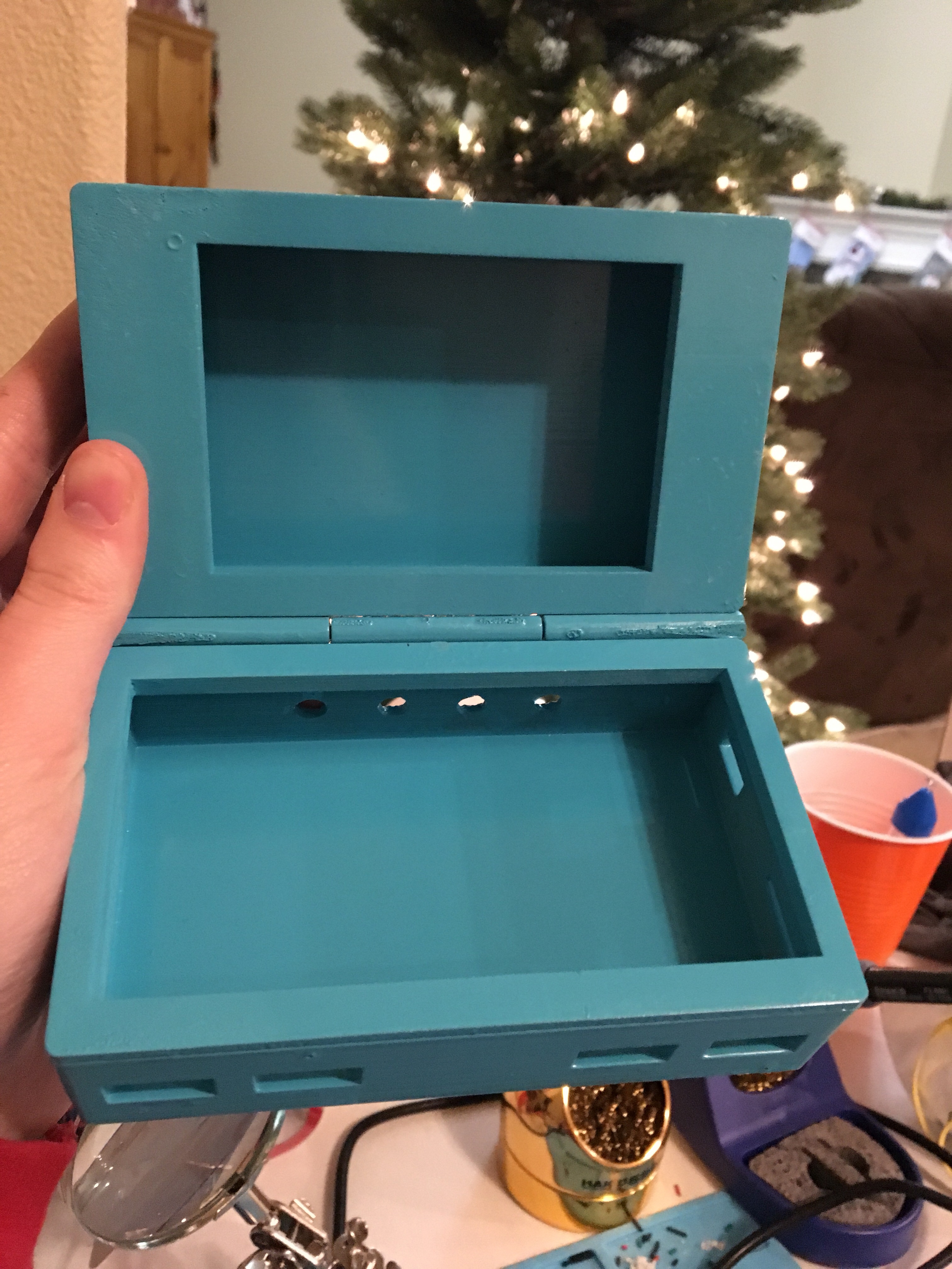
I had to wait three to four days for the case to finish drying, but boy, was it worth it!
I started by desoldering the Li-Po battery from the inside of the bluetooth keyboard, attaching to the leads the 5.5V to 3.3V step down converter.
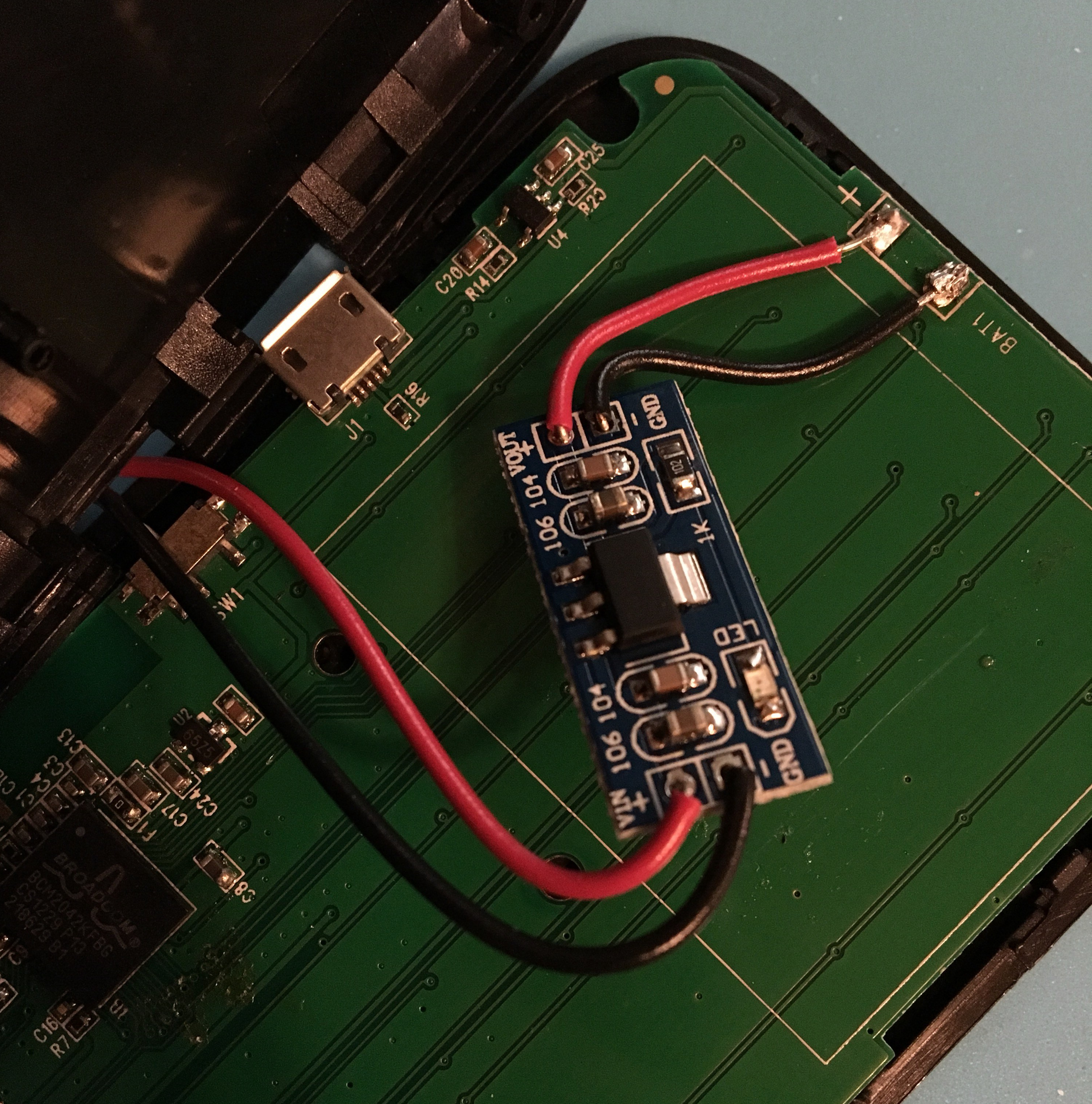
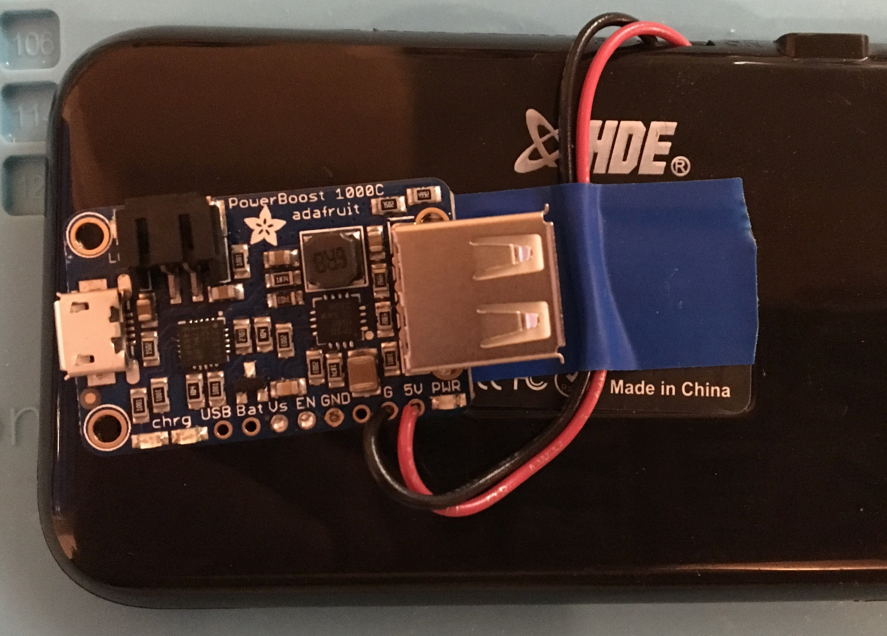
The Vout of the step down I soldered go to the 5V and GND through-holes on the Adafruit Powerboost 1000c.
I left the original USB port on the adafruit powerboost and permanently soldered it to the board.
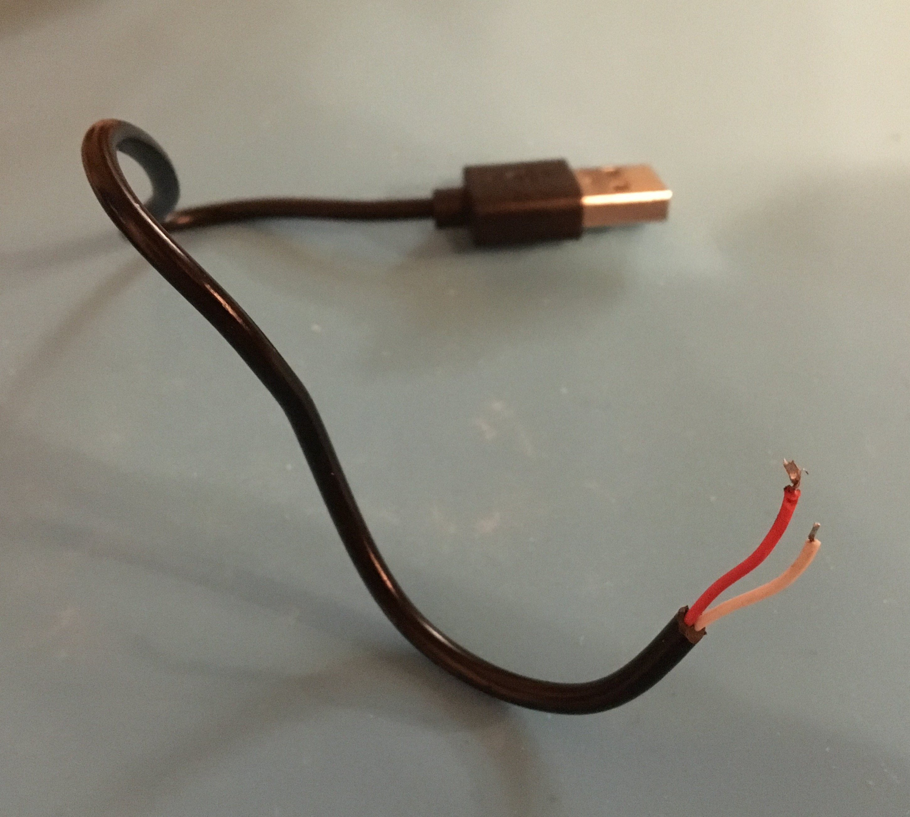
I figured it would be easier to use a well off microUSB cord than to play around with making my own with hookup wire. Fortunately, I had an older (and shorter) microUSB cord that was just for power, not data transfer, so I used that. I wasn’t able to fit the microUSB cord through the holes in the case, so I stripped off the plastic cover to reveal the wires, and I soldered those onto the Pi. I checked with a multimeter which pads were 5V and GND, so I knew where to solder.
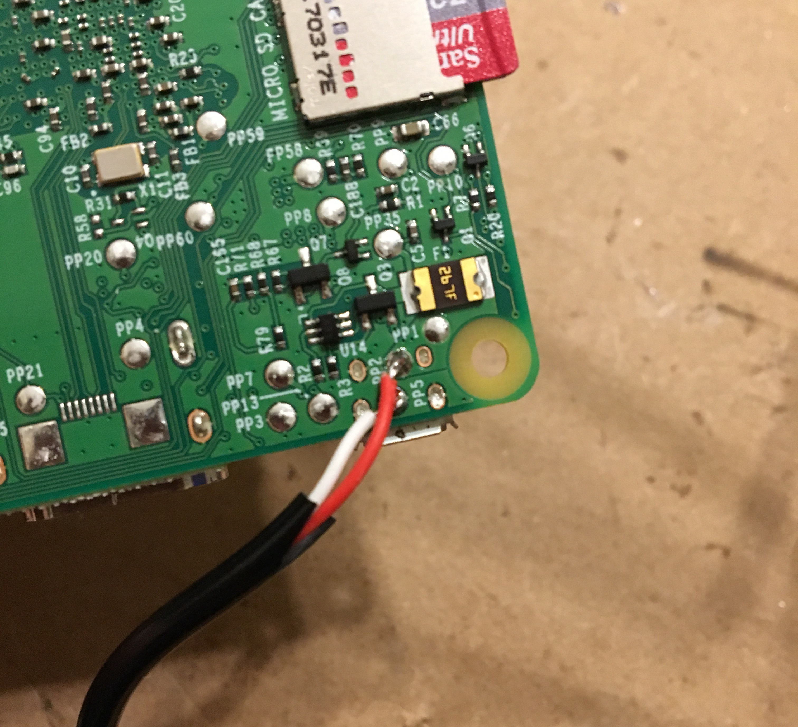
In the end, I decided to forget attempting to get 12 hookup wires through the holes in the case, and I resoldered a 2x20 GPIO header onto the Pi and connected the PiTFT on top of those (like it was intended to be used).
In the case, I drilled two holes for a power light and a low battery light. All of these I soldered from the adafruit powerboost, so I rigged up my 3mm LEDs.
**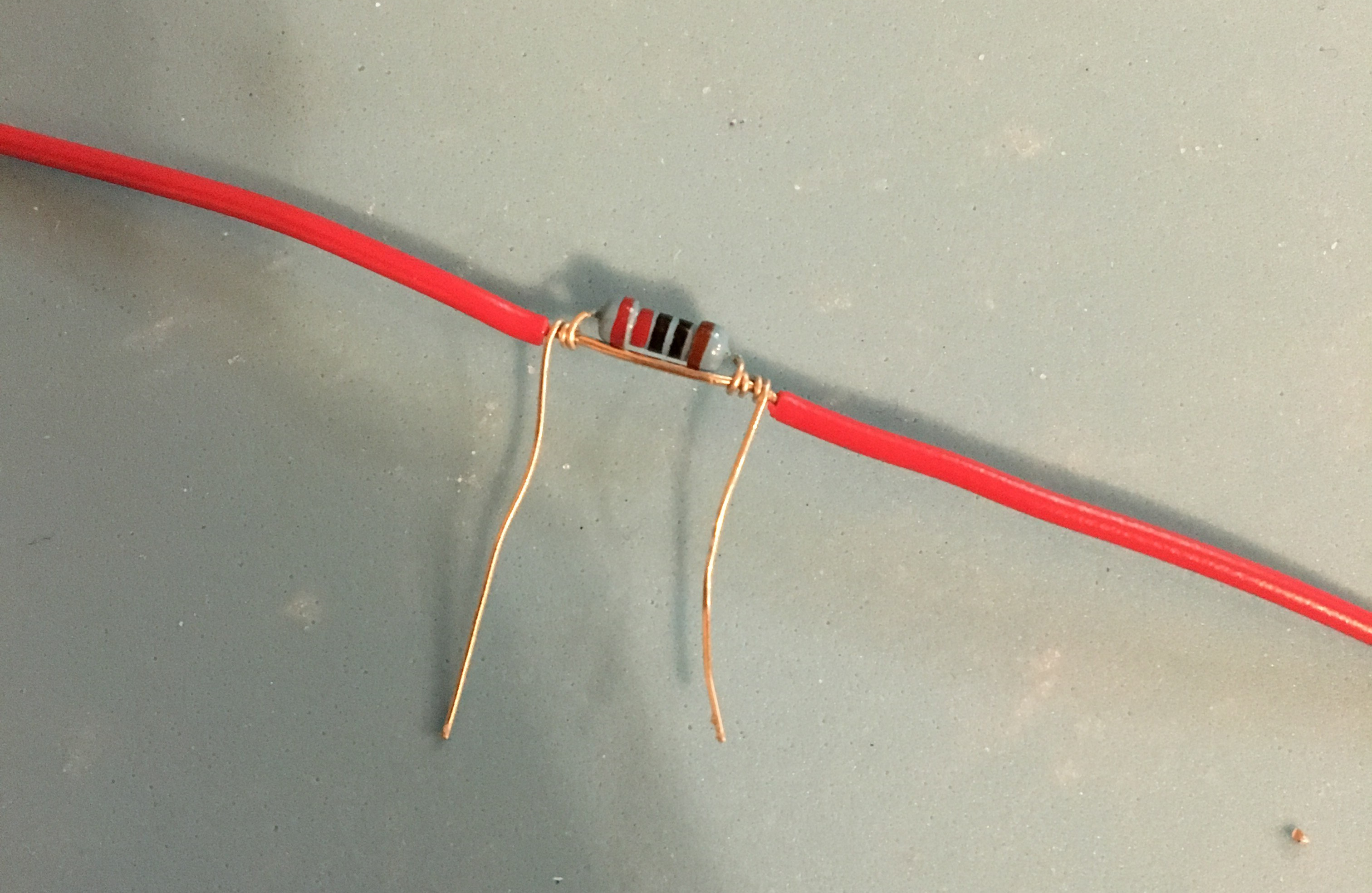 **I wrapped a 200ohm resistor around the stripped wire, soldered the two joints, then trimmed the wires.
I accidentally burned out an LED before realizing that the resistor was in parallel, therefore not allowing the full resistance to get to the LED. I trimmed the wire after that. (below)
**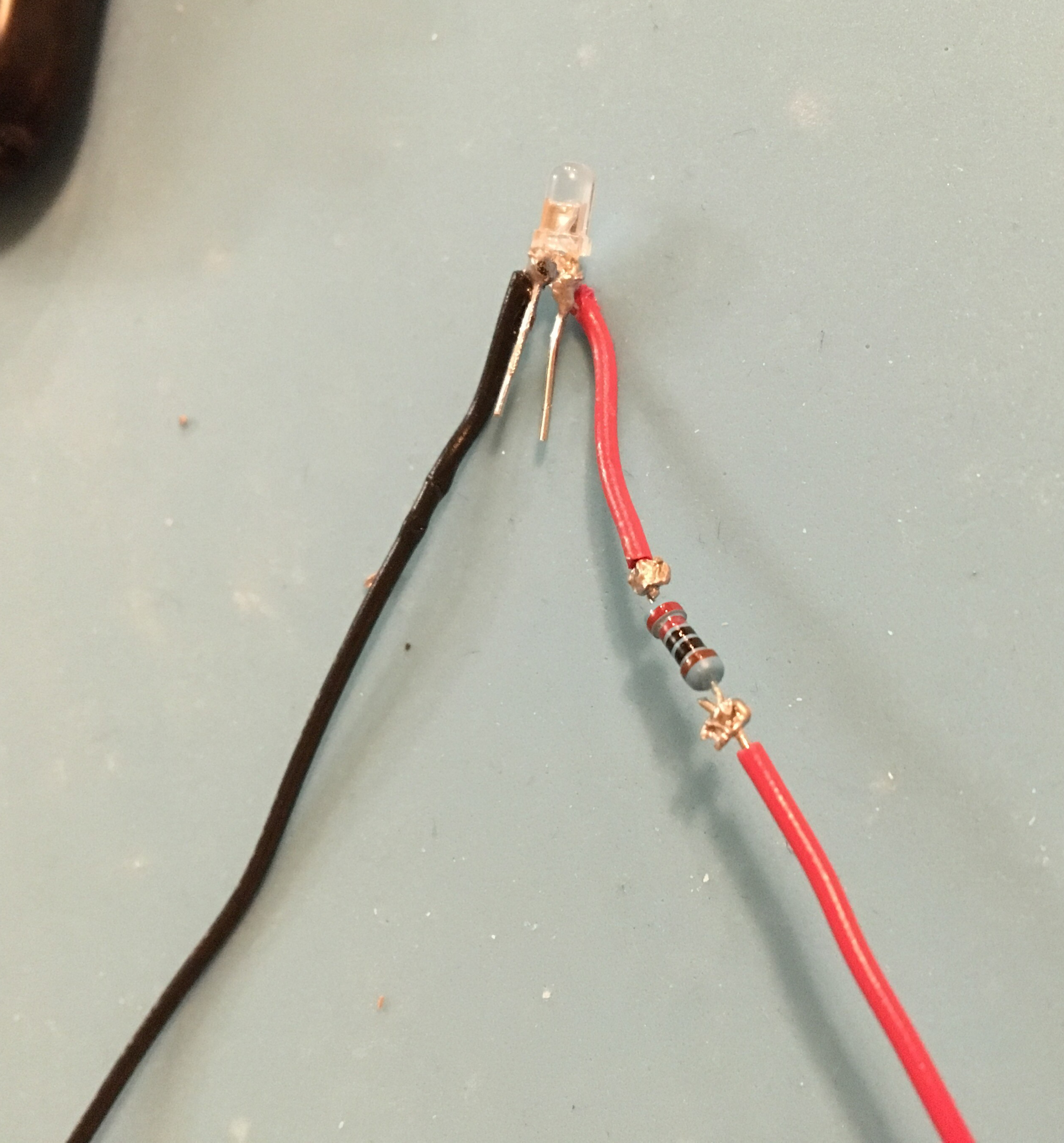 **My solder joints are pretty ugly, I know. But I promise I made them nicer! I also covered that part of the wire in electrical tape.
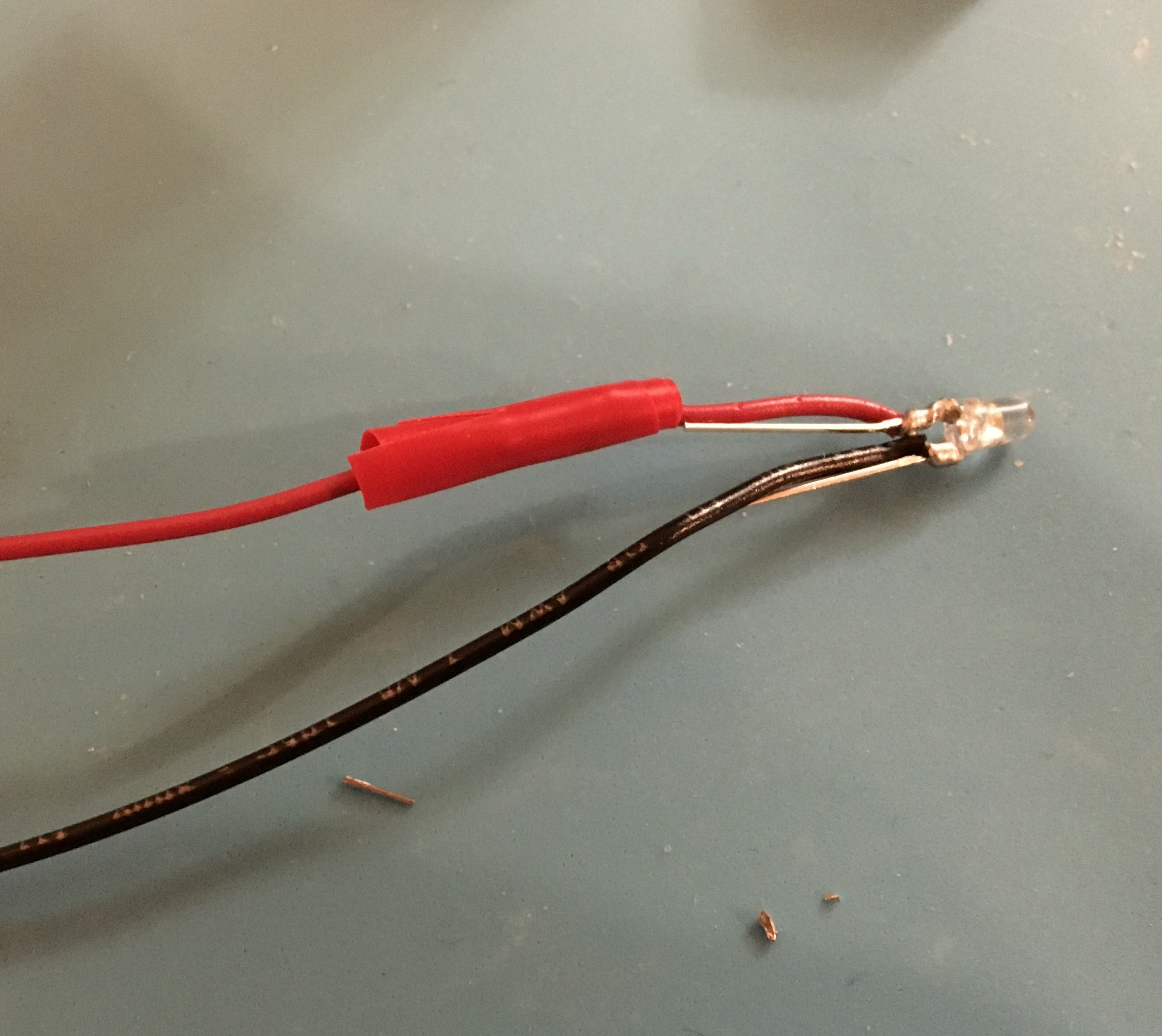
Next was to solder hookup wire to the male USBs:
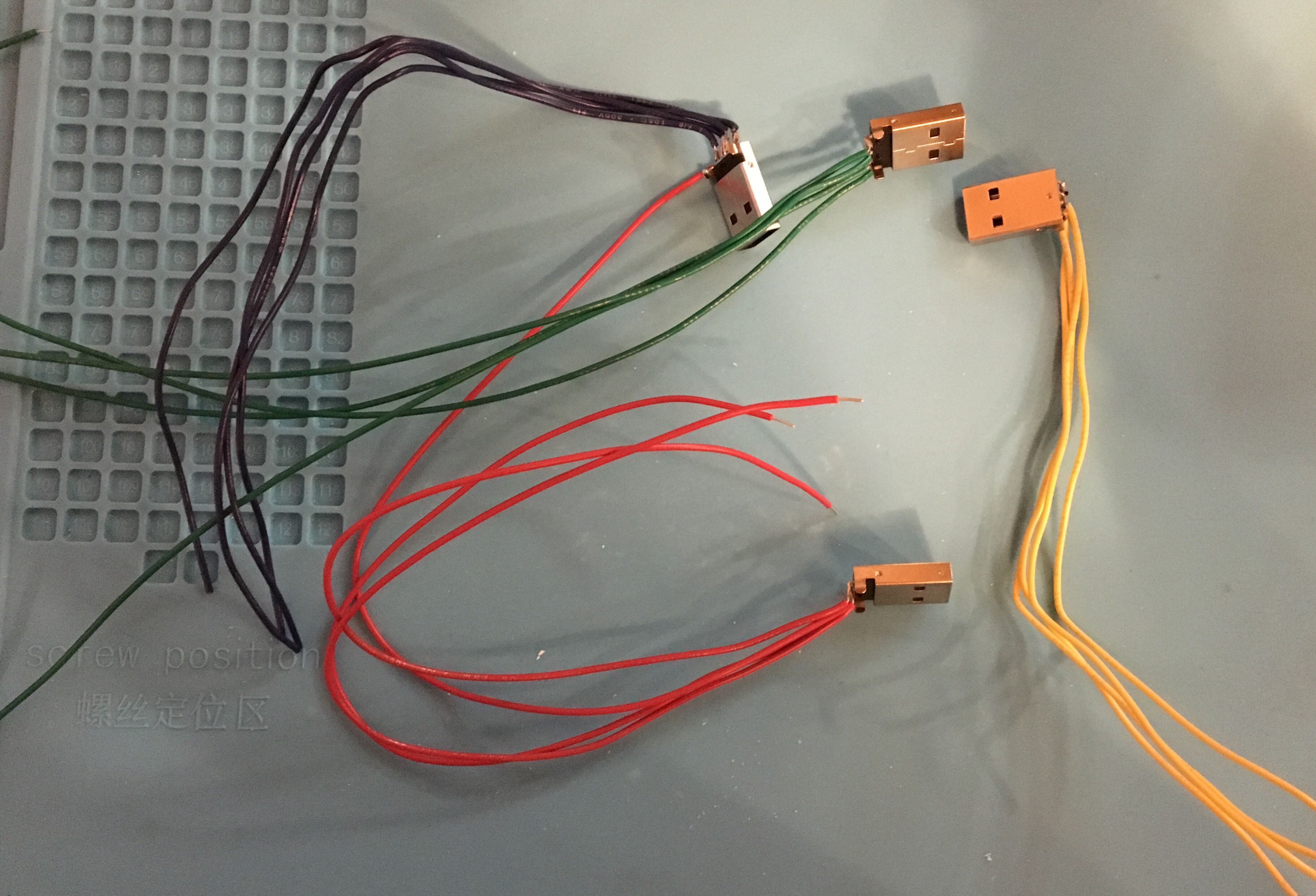
I made each one a different length, since the female USBs were different lengths away.
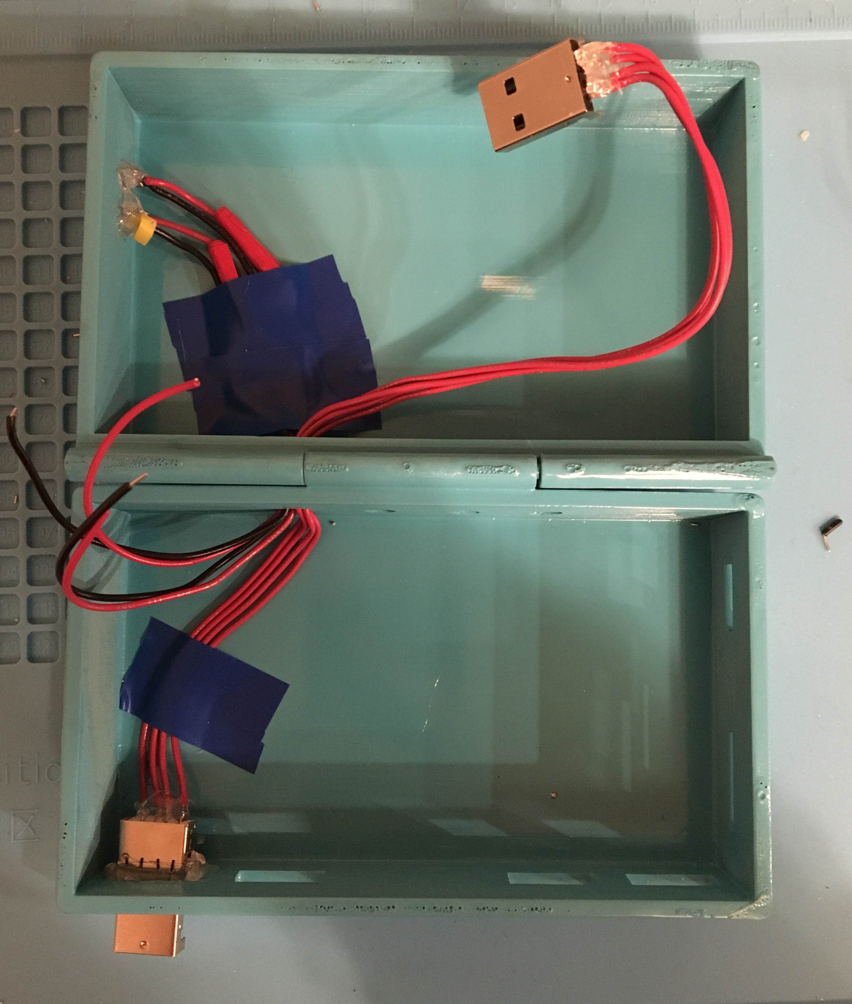 **Hot gluing the solder joints was a life saver for me, because if you bent the connections/wires too much the joints would break off.
**
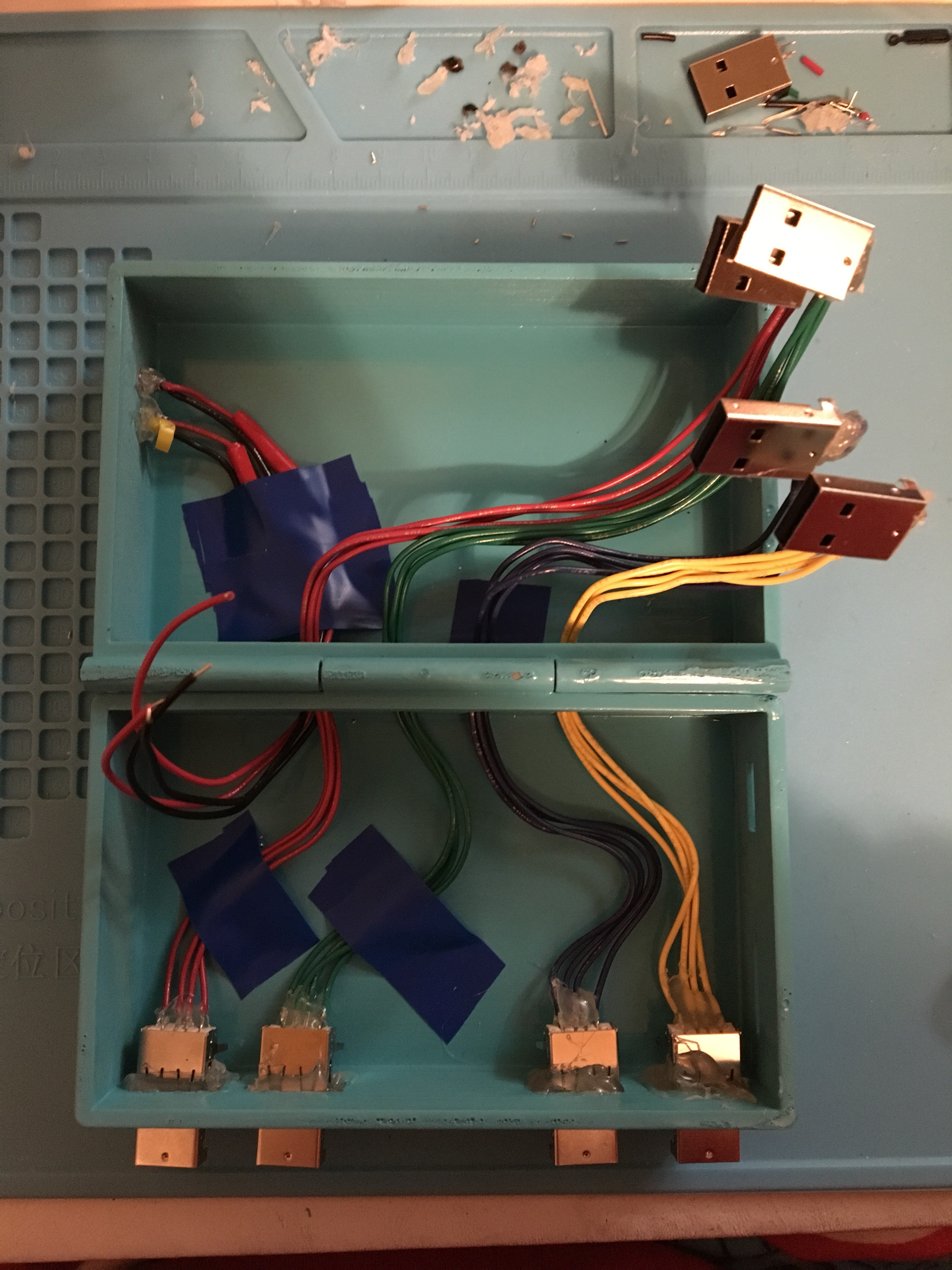
After putting each USB in, I had to bend and twist the wires so the Raspberry Pi and PiTFT still fit snugly in the case, with the wires bent around it.** **
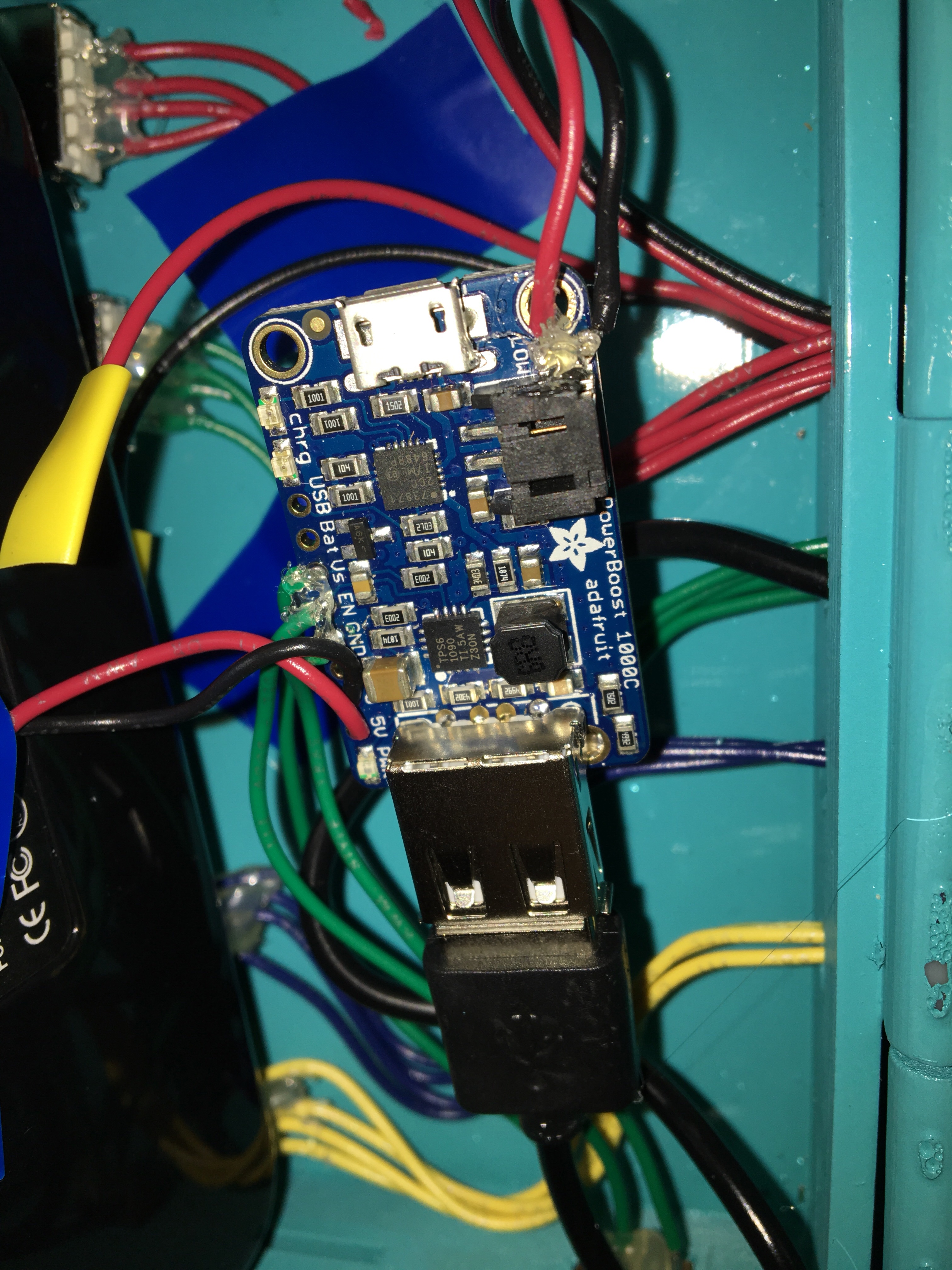
I soldered the 3 green wires to the Vs, EN, and GND through-holes and connected them to the power switch (not shown). The USB cable soldered to the pi I plugged into the socket, and in the top right hand corner I used a multimeter to find the polarities of the Low Battery LED pads, and soldered one of the 3mm LEDs to that.
Under that swarm of wires I placed the LiPo battery and taped it to the bottom with electrical tape.
Soon after, all I had to do was plug in the LiPo to the Powerboost 1000c, put the bevels in place, and watch the magic happen (the tape is on the top because I haven’t decided on a good way to secure the bevel yet).
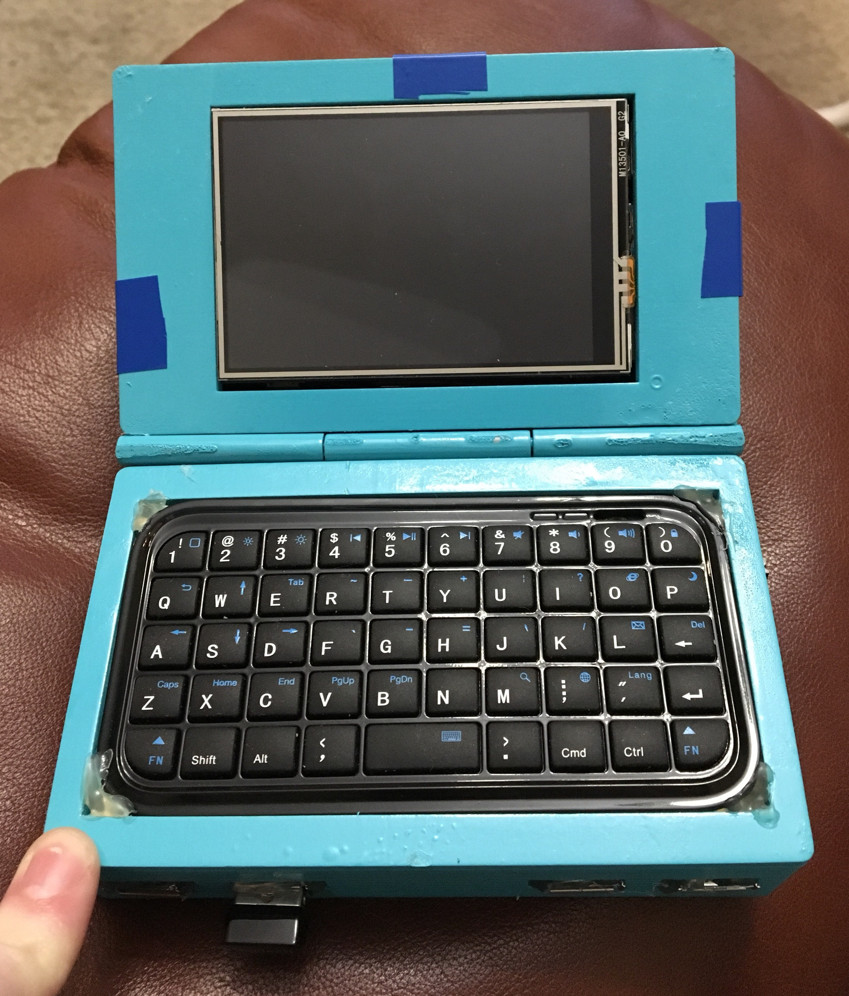
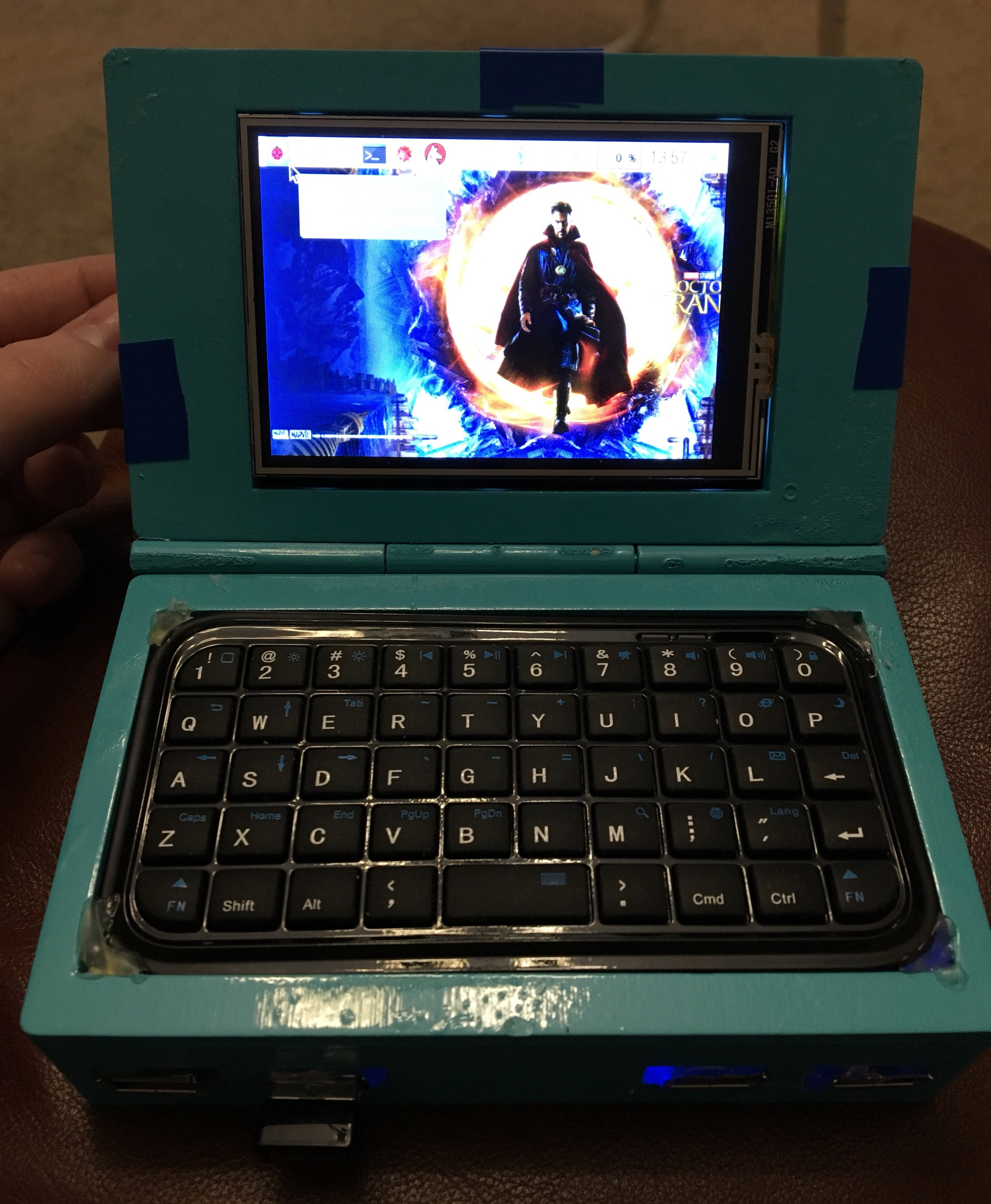
Viola!! My very own portable linux computer. SO EXCITED!!
And yes, that is Doctor Strange as my background. ;)
I’m feeling very accomplished about this, and I hope this walk-through has entertained you or inspired you to make one of your own. If you have any questions about things I did, don’t hesitate to contact me!
Until next time.
{thallia}
