
thallia
Projects, Packages, and Progress, Oh My!
Good Morning, all!
It’s not really morning, but I like that greeting.
This past week has been filled with crazy excitement and many new things! I received two awesome packages filled with electronic components such as logic gates, cords, jumper wires, LEDs, RGB LEDs, resistors, and a breadboard. I couldn’t wait to start working with a breadboard for the first time.
My beginner storage is pretty good for now, but I can tell I’m going to fill it pretty quick and will have to upgrade to something else soon.
The first thing I did was find a guide on how to set up an LED on a breadboard and found this great article. To say I was ecstatic when I built my first circuit was an understatement.

I figured you could put multiple LEDs in a row, because that’s just a bunch of resistors in parallel and it would work, so I played around and got a happy rainbow:

I did learn that breadboard wire links are the same as jumper wires, they’re just specially sized for different purposes. In my package I received an RGB LED (common cathode) as well, which is a Light Emitting Diode that has a Red, Green, and Blue LED in it, and it can make multiple different colors depending on the intensity of each LED. I had no idea how to get it to change colors, so I pulled out my Raspberry Pi for the first time and started experimenting, as I knew there were ways to get an RGB to work with a Pi.

My parents were a bit shocked when they came out and saw I had turned the TV into a monitor, but I assured them it was okay and I wasn’t going to break the TV with my programming.
I didn’t have a usb mouse to connect to my Pi, but I did have a nice mechanical keyboard that I got to highlight the desktop apps, which, fortunately, one of them was a terminal. (I love terminals.) I got the terminal up and running, next I needed to get the RGB LED hooked up to the breadboard and then connect the breadboard to the GPIO pins of the Raspberry Pi.
With this picture, I got the general idea of how to set up the wires in the breadboard and connect them to the Pi:
[caption id=”attachment_566” align=”alignnone” width=”444”]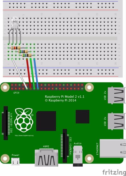 Found: http://www.instructables.com/file/FPKAEQ2IGTYC14Z/[/caption]
I must admit, it took me way too long to figure out that I had a Raspberry Pi 1, not a Raspberry Pi 2. Heh. Once I discovered that, I could effectively attach my jumper wires to the appropriate GPIO pins on the Pi, using this diagram:
[caption id=”attachment_571” align=”alignnone” width=”390”]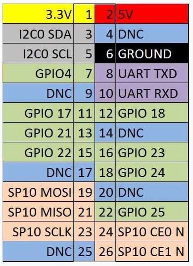 Raspberry Pi I GPIO Chart[/caption]
The code I used required me to attach my cathode (the longest pin) to pin 6, GROUND. The RED pin I attached to GPIO 12, GREEN I attached to GPIO 16, and BLUE to GPIO 18. Here’s a picture of it all set up (from two different angles).

Once I connected the wires right, I could start finding code to get this LED to work. After searching for code that worked with a Raspi 1, I stumbled upon this website by a guy named Henry Leach. Boy, was I glad to find his post. He showed his calculations about resistors and picking the right values to get the brightest colors, and then nicely shared his code that cycled through a variety of colors with his LED.
I don’t know anything about Python (yet), but I went with it because I wanted to get this thing working. I typed in all the code (which was painstaking, because I use a dvorak keyboard layout, but it was in US on the Pi. That took a while…) into the terminal text editor, nano. To get there, I opened a terminal and executed nano rgb.py

Once I finished typing that all out, I assumed IDLE was a Python Shell, so in a terminal I executed idle . From my experience with a Forth terminal, I knew if you wanted the code to be used in that session you had to use include filename.fth to use your code within the shell. I assumed import did the same thing, and viola, it worked! I had some syntax errors but once I fixed those and ran the program, I got a wonderful result:
I think the lights were a bit shaky at certain colors because I only had 1k Ohm resistors, so once I get my package of 30 different types of resistors today in the mail I’m going to try this project again to see if it makes a difference.
Now my goal is to replicate this in C code, as I’m going to learn it. After that, I’m going to attempt to get the LED to change colors and respond based on the waveforms of music that is playing, and eventually put this tech in the laminar water fountain I’m building with my friend.
I’ll put a post up about the fountain soon, we just bought the first installment of the supplies and materials, and once we start building it I’ll put up a tutorial type post.
Before I wrap up this post, in other news, I received a mandolin from my Nana as an early birthday present and I couldn’t be more excited](https://thalliatree.files.wordpress.com/2017/07/img_4672.jpg)
I’ve been teaching myself some scales, and I’m working on the Irish Washerwoman melody picking. I’m thinking of naming it Henry. What do you all think? :)
Cheers!