
thallia
Reverse Engineering a Broken Diffuser Circuit
One rainy day my essential oil diffuser broke, and I was sad. Until I realized I could tear it apart and figure out how the circuit worked! I recruited Gector to help me again, and we managed to reverse engineer the whole thing in a few hours.
The top of the circuit looked like this:
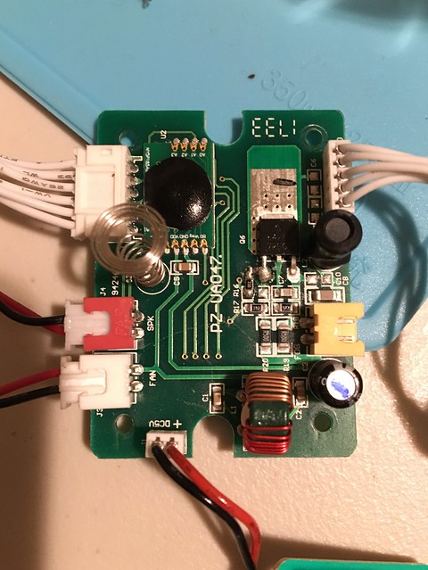
So we thoroughly went through with a multimeter and figured out what traces connected to each other.
We identified these first:
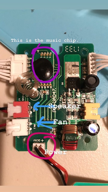
You can see the music chip, the speakers, the power, and the fans pretty easily.
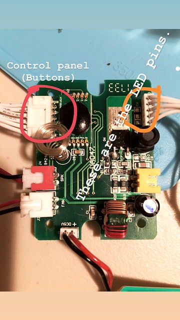
Here, there are the LED pins, which connect on the opposite side of the board to some transistors and a microcontroller. You can also see the pins to the buttons that power the diffuser.
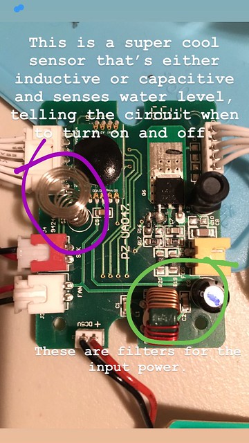
Here is the capacitive or inductive sensor that senses the water level and tells the diffuser when to trigger the automatic shutoff when the water runs out.
Finally,
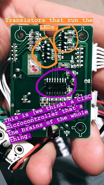
We identified what kind of pins are on the microcontroller, where the Vcc and Ground were, and diagnosed what brand it could potentially be.Figures it’s probably a CISC microcontroller, since it has a ton of output pins and not that many input pins. :)
We thought it was potentially the ultrasonic part that was broken, but after testing some of the pins it seems as though either the microcontroller that triggers the ultrasonic diffuser chip is broken, or the transistor between the two is dead. We couldn’t quite figure out which.
Otherwise, that was a super fun project to identify all the components and figure out how the circuit worked as a whole.
Until next time!
{thallia}