
thallia
LinuxCNC with Plasma Cutter: Adding Torch Height Control
- What is LinuxCNC?
- Scope of our Project
- Lack of Instruction
- Main Circuit Diagram
- Assembly
- HAL 9000
- HAL Terminology
- Types of signals & pins
- Basic Syntax
- THCUD
- Troubleshooting
- Sensor Troubleshooting
- Limit Switch
- Finale
What is LinuxCNC?
LinuxCNC is an open source software for CNC machines such as mills, routers, engravers, and cutters. It interfaces between the machine/software and interprets the gcode files for use. For our situation, we were using a plasma cutter! There is a plasma cutter I often run in the machine shop for Gector’s family business, Whitlox Forges, a business for building forges for blacksmiths.
Scope of our Project
The plasma cutter worked great, but often the sheet metal we cut was slightly bent, or the rims the metal sat on weren’t completely flush. Because of this, the torch wouldn’t always light for cutting at different places on the sheet metal, or it would drag on the metal and fail to cut at all.
Because of this, we obviously needed some kind of torch height control system, so the torch knew where it was with respect to the metal. Gector’s dad bought the supplies, and hired us two to set it up and figure it out.
We used the sensors from PoLabs: Torch Height Controller - PlasmaSensOut
There are datasheets for the pinout and basic circuit here.
With that, we had the basic outline of what we needed to do for the project–set up the circuit and get it interfaced with LinuxCNC.
Lack of Instruction
As we got into the project, we realized there was virtually no instructions on how to use the documentation for the HAL programming with LinuxCNC, nor great instructions on how to connect the sensors to the software such that it would recognize and use it. We searched through tons of forum posts, github files, and code to try and figure out the generic outline of what kind of HAL code we needed to write, but ended up having to reverse engineer other people’s configuration files to get ours working correctly.
Because of this, Gector and I co-wrote this post to try and provide a thorough outline and documentation of our entire process for those needing to set up or troubleshoot something similar for their machine.
Note: Our setup is with stepper motors, not servo motors.
Main Circuit Diagram
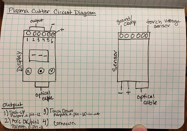
We got a good idea of what the circuit should look like by deciphering the datasheet, which you can find here.
There was a great chart we used to identify which pins went where–in the terminal on the sensor display as well as for which pins connected to where on the optocouplers on the breakout board we have.

For reference:
| Terminal Pin | Breakout Board Pin (code) | Function |
|---|---|---|
| 1 | parport.0.pin-12-in-not | Torch Up |
| 2 | parport.0.pin-11-in-not | Arc-OK |
| 3 | parport.0.pin-10-in-not | Torch Down |
| 4 | Common | |
| 5 | Ground | Ground |
| 6 | Vcc (5V) | Voltage |
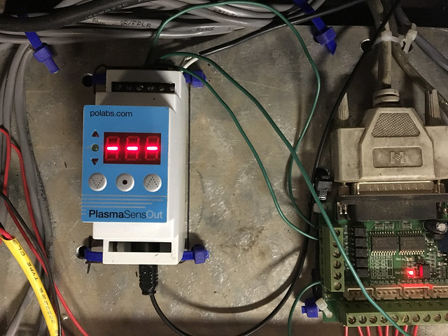
As you can see, pin 1 connects to breakout pin 12 in our circuit (open pins for configuration), and I put the line of HAL code in there that represents the pin as well, for each pin on the sensor display. You can read more about how the HAL coding works in the next section, but this was the overall configuration of our circuit and pins.
Assembly
For the assembly of the circuit, we first made a copper wire loop to go around the terminal of the plasma cutter box, it measured the voltage of the torch as it was cutting.
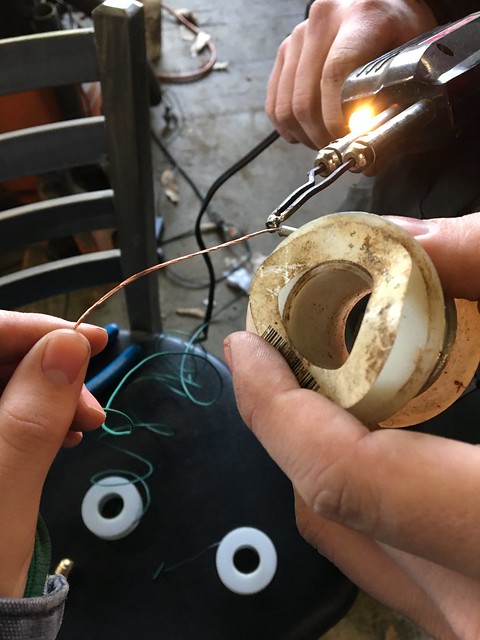
You can see how we attached it to the sensor, towards the back of the threaded part of the port.
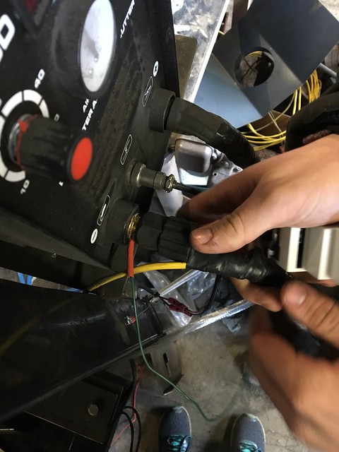
Below is the final attachments to that part of the sensor set, the optical cable, the power and ground, and the other green wire was for clamp (opposite to the sensor measuring the voltage of the torch.)
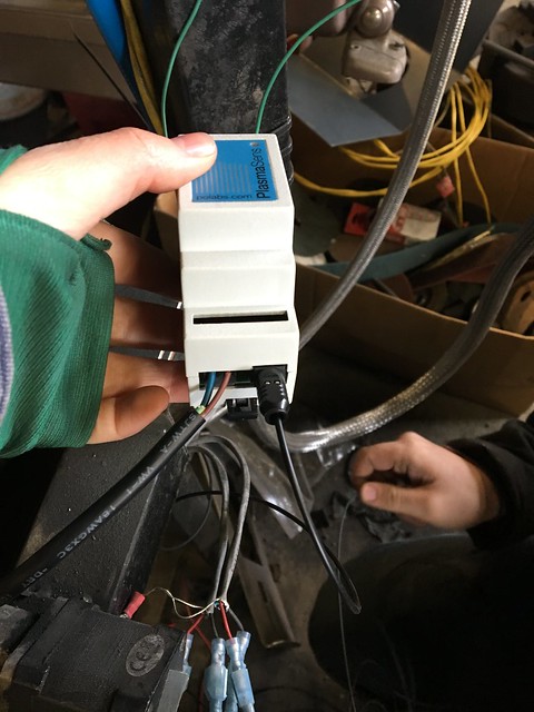
Next, we wired up the display.
Troubleshooting the Circuit
When we went to put the pins in the board with the optocouplers, nothing would work at all. It turned out the optocouplers were a common anode device instead of common cathode, like we originally thought. All the switches were open, and needed a ground signal when closed, but we were doing the opposite–assuming they all had ground and needed a 5V signal when the switch closed.
It took us a few hours to troubleshoot that while trying to get the circuit display to work, because nothing we connected was triggering. Lesson learned: always check that the diode is in forward bias.
HAL 9000
HAL
HAL stands for Hardware Abstraction Layer. At the highest level, it is simply a way to allow a number of building blocks to be loaded and interconnected to assemble a complex system. The Hardware part is because HAL was originally designed to make it easier to configure LinuxCNC for a wide variety of hardware devices. Many of the building blocks are drivers for hardware devices.
Throughout the explanation of HAL we have here, our code is at the very bottom as an example for you to follow along. We’ve linked the specific files in our GitLab repository, as well as pasted the specific segment for reference.
HAL Terminology
| Word | Definition |
|---|---|
| Parport | Parallel port |
| Signal | Virtual jumper wire |
| Parameter | Input or outputs designed to be set once |
| Pin | Virtual or physical pin defined in HAL |
| Component | Building block for HAL workings |
| THC | Torch Height Control |
| HAL | Hardware Abstraction Layer |
| Function | Code that actually performs operations in a component |
| Thread | List of functions that get run at certain intervals |
Signal
In a physical machine, the terminals of real hardware components are interconnected by wires. The HAL equivalent of a wire is a signal or HAL signal. HAL signals connect HAL pins together as required by the machine builder. HAL signals can be disconnected and reconnected at will (even while the machine is running).
Component
Each HAL component is a piece of software with well-defined inputs, outputs, and behavior, that can be installed and interconnected as needed.
Quotes pulled from: http://www.linuxcnc.org/docs/2.7/html/
Types of signals & pins
bit |
Single TRUE/FALSE or ON/OFF value |
float |
A 64 bit floating point value |
u32 |
32 unsigned value, 0 to about positive 4 trillion |
s32 |
32 bit signed value, -2 trillion to +2 trillion |
Basic Syntax
net
One of the most common commands used in HAL scripting is the net keyword. The syntax and explanation is as follows:
net signal-name pin-name <optional arrow> <optional second pin-name>
Where signal-name is the name of the virtual wire that the HAL layer will use to connect pin-name and the optional other pins together. Signals are essentially jumper wires with names you can use to attach pins. Notice that only the first two arguments to net are required, the arrow (<= or =>) and the second pin is optional. This makes it possible to either bind a single pin to the signal/jumper wire or have the signal connect multiple pins. The direction of the pin is defined in it’s HAL definition, but it’s usually indicated in the pin’s name. If the pin’s name is parport.0.pin-10-in it would write the signal value but if it was parport.0.pin-16-out the signal would write to the 16th pin of the parport. Note that net cannot be used with parameters, which are usually set once using a setp command.
net a-signal estop-pin
Assuming estop-pin is an input pin, a-signal would then inherit the value from estop-pin even if it changes while the program is running. It’s worth noting that a signal can have many inputs, (many pins setting the signal’s value), but a signal can only have one output pin or one input/output pin.
net torch-down thcud.torch-down <= parport.0.pin-10-in-not
In this case thcud.torch-down and parport.0.pin-10.in-not are being tied together with the torch-down signal, which is acting as a jumper wire.
To recap shortly what happens:
The pin-name, thcud.torch-down, is assigned to the signal-name, torch-down (which is user specifiable). After torch-down inherits the value from thcud.torch-down, that value is passed (or tied) to the second pin name (parport.0.pin-10-in-not).
addf
Adds a function to a thread. You must add a function to a thread for it’s code to ever be executed. Usually there are two main threads, servo-thread and base-thread. The base thread is the high speed one, handling step pulses and reading/writing the parport. The servo-thread handles the slower and more computation heavy calculations like the motion controller, and all floating point math.
addf <function> <thread>
For THCUD, we load the thcud function from the thcud component, which goes into the servo-thread, and it’s code gets executed.
addf thcud servo-thread
setp
Sets the value of a pin or of a parameter. Will throw an error if the data types of the value given and of the parameter are different types. You can’t use setp on a pin that is already connected to a signal. In other words, you can either connect two things together using net or you can set a pin to a value once using setp
setp <pin/parameter name> <value>
We used setp to configure the correction velocity and cornering-speed tolerance values of thcud, and to enable the function so it can run.
setp thcud.correction-vel 0.0001
setp thcud.velocity-tol 10
setp thcud.enable true
THCUD
There are two torch height control components available for use in linuxcnc, one is called thcud and the other is just thc. The thc component is designed to use a signal from a MESA Torch Height Controller, whereas the thcud just uses the signal from any device that can output up, down, and “arc okay” signals. We used the thcud component because the hardware for it and the setup seemed a little easier, and a little cheaper.
Troubleshooting
Adding the wrong function
When we were sure we had gotten the circuit working completely and the trigger pins functioning, we tested out a basic cut, but the torch dragged on the metal and wouldn’t move up or down.
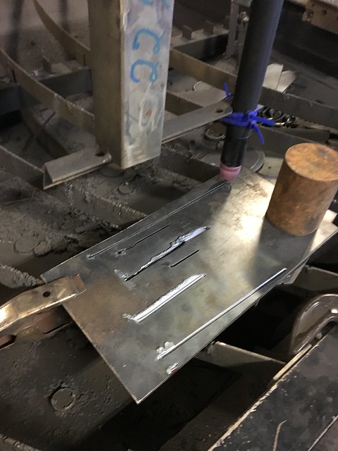
As you can see above, the first few cuts towards the bottom of the metal didn’t even cut through. We scoured the HAL file, the INI file, and apparently you have to add the right function to the servo-thread. Before, we weren’t adding the function thcud to any thread, and the LinuxCNC would throw an error and not start the program.
After we browsed through other people’s configuration files, we found that we needed to have this line of HAL:
addf thcud servo-thread
Once we added that, LinuxCNC booted up, and we had a successful cut! (as you can see on the top of the metal in the image above).
Torch wouldn’t fire
Another problem we encountered quite a bit was our torch didn’t fire every time, even if it was touching the metal correctly. We spent hours trying to get it to work, to no avail.
Eventually, we figured out it had to do with the gap between the electrode and the nozzle tip. To fix that, we just had to put the electrode in less far than we had been, and the torch works almost 100% of the time now.
Things to mention:
When you set thc.velocity-tol in the HAL file, it doesn’t take into account the feed override percentage that you set in the Axis GUI. For example, if you set the velocity-tol to 2%, the maximum feed override you could set would be 98% before it completely disables the torch height control.
If the thcud function doesn’t appear to be affecting Z axis movement, make sure you have added it to the servo-thread and are passing Z control through the thcud component (last 3 lines of our code shown below).
Our Code (on gitlab)
We uploaded and backed up our written code on Gitlab for reference.
Here’s the gist of it though:
loadrt thcud
addf thcud servo-thread

net arc_ok thcud.arc-ok <= parport.0.pin-11-in-not
net torch-up thcud.torch-up <= parport.0.pin-12-in-not
net torch-down thcud.torch-down <= parport.0.pin-10-in-not

net torch-curr-vel thcud.current-vel <= motion.current-vel
net torch-req-vel thcud.requested-vel <= motion.requested-vel

setp thcud.correction-vel 0.0001
setp thcud.velocity-tol 10
setp thcud.enable true
setp thcud.torch-on true

net zpos-cmd thcud.z-pos-in <= axis.2.motor-pos-cmd
net thc-pos-cmd thcud.z-pos-out => stepgen.2.position-cmd
net zpos-fb axis.2.motor-pos-fb <= thcud.z-fb-out
In our case we decided not to use the torch-on handling in thcud, at least for now. For now it’s just set to true, as if the torch was always on. This way only arc-ok is necessary for the thcud component to work.
Sensor Troubleshooting
Towards the end of the coding process, we ran into some circuit issues. The sensor display we had should have been displaying three dashed lines, like so:
But it kept flickering, and displaying E-1 on the little screen, like so:
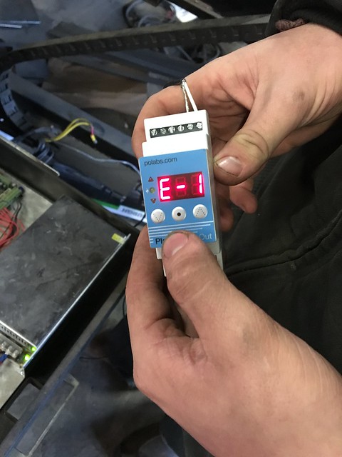
In the datasheet we found that E-1 means communication error, but it didn’t offer any solutions on how to solve that. We checked and double checked the optical cable, in case that provided any issues, but that didn’t seem to change anything. We checked the connections to the torch, but it was all solid.
Next, we checked the pins on the sensor, pin 5 and pin 6, Vcc and GND. The screws were all really loose on those, and as soon as we tightened them real good, the error message disintegrated. :)
Limit Switch
We added a Z limit switch to the machine, so when executing a file and before lighting the torch, the plasma cutter will touch down on the metal, zero itself, and then fire the torch with that new Z axis at zero.
Finale
All in all, this was a super fun project that Gector and I did together.
You can see the little arc-ok, torch-up and torch-down GUI gector added in this video here and how it reacts throughout a cut:
And what it looks like with the motor spinning on top:
If you have any questions, don’t hesitate to email one of us, or find us on my Discord server and one of us would be happy to help you out.
Until next time!
{thallia} & gector